The PadPuls converter is used whenever necessary to convert pulse outputs from water meters, gas and electrometers to the M-Bus bus. The converter is made in multiple versions depending on how many pulse inputs you can connect to it. The configuration is completely identical for all variants. The maximum number of entries is 4.
Necessary resources
- Install MBCONF software on your PC / Laptop.
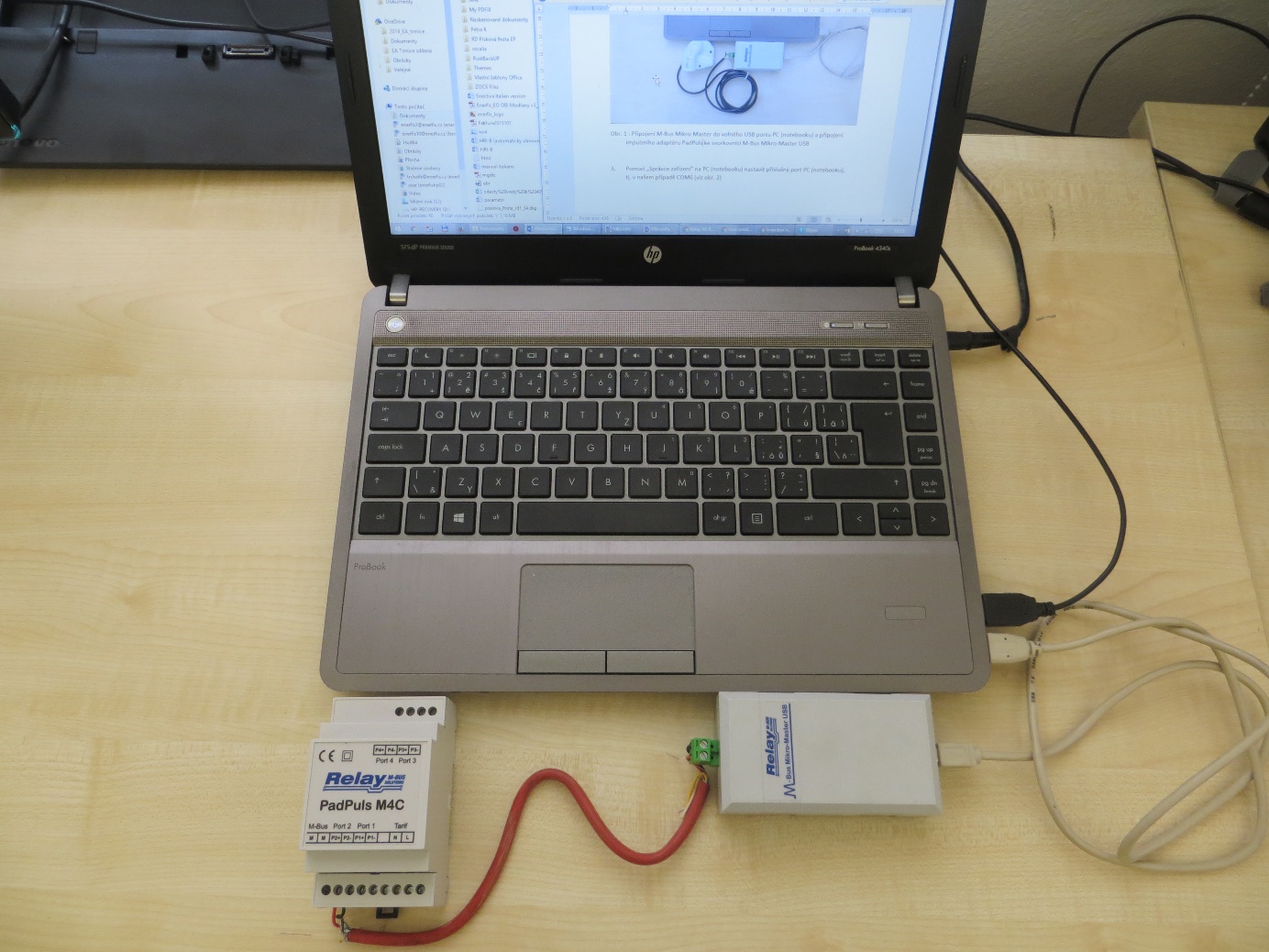
- Connect M-Bus Micro-Master to a free USB port on the computer, such as COM6 (see image).
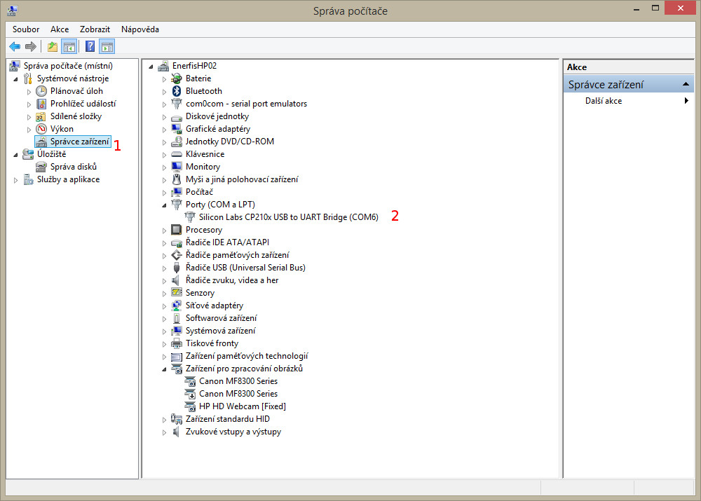
- Use the Device Manager on the computer to configure the appropriate PC port, ie in our case the COM6 (see image below). On which COM port is connected to MikroMaster, you can check it with the Device Manager / Device Manager on your Windows.
- From the Device Manager we must open the previous port and in the tab port configuration have the following parameters:
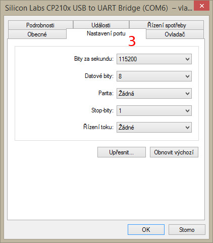
| Option | Field |
|---|---|
bit/sec |
115200 |
datagram bit |
8 |
parity |
none |
stop bit |
1 |
flow managment |
none |
-
Connect the PadPuls Adapter (M-Bus Terminals) to the USB M-Bus Micro-Master terminal (see first image).
-
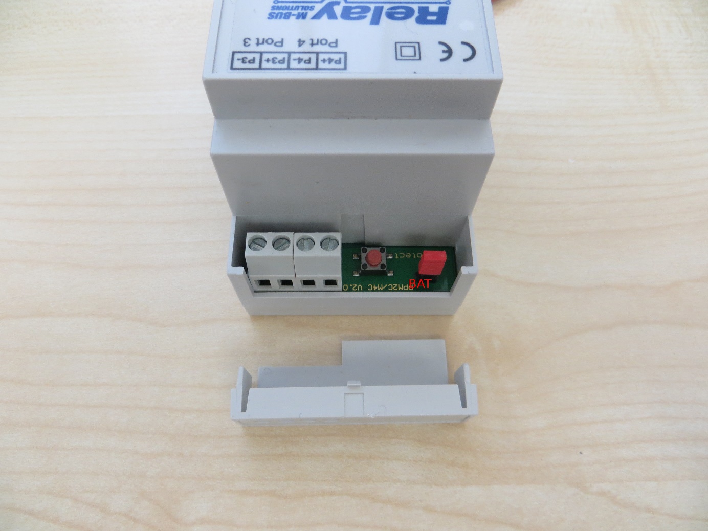
Activate the PadPuls adapter. Remove the adapter top cover and the BAT tag jumper on both pins. (see picture below)
-
Open the program MBCONF. Which can be downloaded from the Internet or send technical assistance to the Energetic Team.
-
Make basic settings:
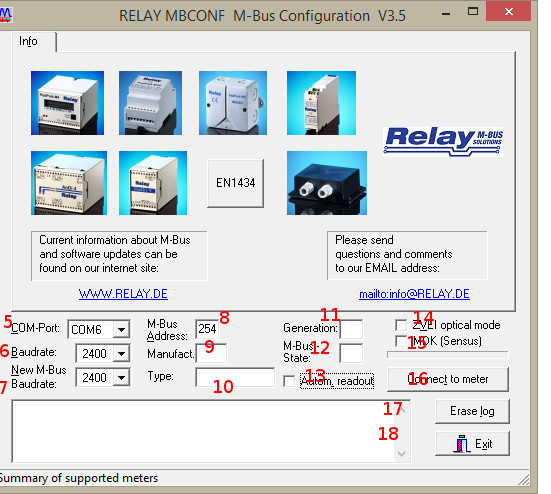
- Set port number the same as on PC (5).
- Set the communication speed to
2400 Bd(6) - Setting the speed according to (7) is not necessary (it is automatically configured from the parent device).
- Set M-Bus address to 254 (8). 254 means multicast. This is the address by which all devices respond, it is used in cases where you do not know the address. You can not use it when there are more devices on the bus.
Manufact= loaded does not need to be changed. (9)Type= loaded does not need to be changed (10)Generation= loaded does not need to be changed (11)MBus state= loaded does not need to be changed (12)Autom. Readout= is an option, if the activation software always reads the data after writing (it is useful to check the accuracy of the programming - 13).ZVEI Optical Mode= If this mode is enabled, the device equipped with the optical interface and the M-Bus protocol in accordance with EN 1434-3 can be scanned and programmed using an optical read head. We do not use it in Enectiva projects. (14) -MDK (Sensus)= this is used for readings with Sensus MDK (15). -Connect to meter= this is used for data requests from the connected device (in our case PadPuls - 16). -Erase log.= Delete the contents of the log. (17) -Exit= exit the program and save the current settings. ** (18)**
After connecting and setting parameters, press connect to meter.
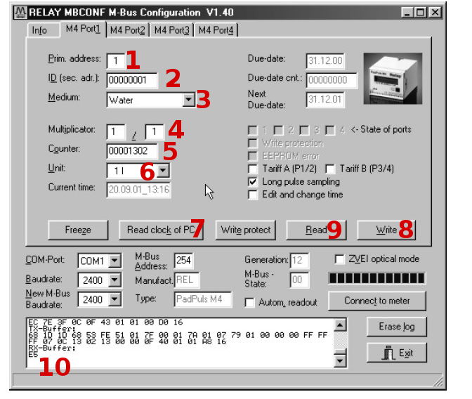
Depending on the variant of the PadPuls converter, the interface with one or four ports at the top appears. To set this look at the image of the settings Port 1.
- Fill in the primary address. Each device connected to the M-Bus bus must have a single address and a single primary address in the range of 0-254 (number 1 in the previous image).
- Fill in the secondary address, usually the serial number of the counter, and this is the number by which the counter is read in Enectiva. (No. 2). Even the secondary address must be unique next to the bus.
- Select the type of power measured in Port 1. In our case water.
- The numbers 4, 5 and 6 are the most important of all converter settings. Here we adjust the size of the pulses individually using the Multiplicator, then the current status of the meter (counter) and the unit in which we are reading it. Example, regarding the image, we say that a pulse is equal to a liter and the meter is currently at 1302L.
Examples of multiplier settings
Example 1
The water meter has 45,120 liters and a pulse = 10 liters. You have 2 options to configure the converter:
- Unit = 10L, Multiplicator = 1/1, Counter = 4512 (the last zero we did not mention because you have set it to jump after 10 liters).
- Unit = 1L, Multiplicator = 10/1, Counter = 45120 (x 1L)
Example 2
The electrometer has 78346 kWh and 64 pulses = 1kWh
- Setting: Unit = 1kWh, Multiplicator = 1/1, Counter = 78346 (x 1kWh)
Example 3
The electrometer has 112,345kWh and 1,000 pulses = 1kWh
- Setting: Unit = 1Wh, Multiplicator = 1/1, Counter = 1123454 (x 0.001Wh)
Examples of how to set up indirect measurements of meters carrying a metering device
- You need to synchronize the time and therefore press the button labeled with a 7.
- Once you have all pressed, press
Writeand all the configured values are written to the transmitter. - It is always important to verify that it is written, so press
Readto verify it. You will also see the status of the counter, so you can verify that you have configured the transmitter correctly.