You will use the M-Bus splitter if you want to read counters simultaneously from two central units (M-Bus Master). Typical examples of using heat distribution meters (city heating plants) that have been equipped with an M-Bus output for CHP and want a meter of such characteristics connected with the Enectiva system. In this case it is necessary to divide the M-Bus output from the meter into two M-Bus outputs.
The M-Bus splitter can separate a bus with a maximum of 4 M-Bus counters.
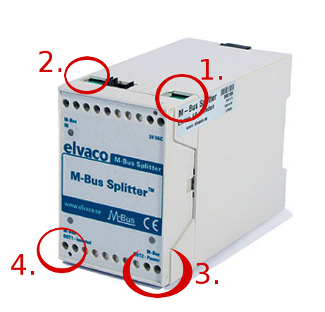
How to connect
- If you want to divide a bus with more than 1 meter, it is necessary to connect the 24 VAC to the terminals marked in the image above. If you only have one meter on the bus, these terminals are empty. Only the M-Bus 2 input (number 3) output to which one of the M-Bus Master is connected will be used.
- Connect two bus terminals (M-Bus IN) to the bus you want to divide. It can be with one of the four counters.
- For the M-Bus OUT2 power terminal, connect the bus you want to power our M-Bus splitter in case the 24 VAC source is not used in terminal 1.
- Connect terminal 4 (M-Bus OUT1 - Isolated) to the new bus for example S Enectiva Maestro. (Master is just another name for a communicator, hub or central unit).
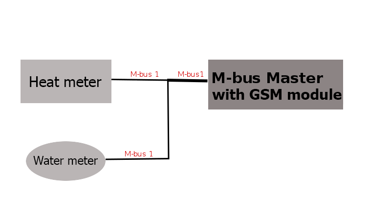
Typical Usage and Involvement Situation
You have a connection from the heating plant, see back image. The calorimeter and water meter are connected to their master M-Bus and read data from the mobile network (GSM Modem).
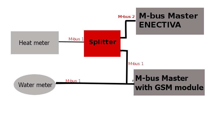
You only need to read the calorimeter in Enectiva, ie the bus section (M-Bus 1 cable) with the calorimeter needs to be separated into two separate segments using a splitter. There will be the situation in the picture. The M-Bus cable is separated in M-Bus in the original master and M-Bus 2 in the master Enectiva. (Master = Central Unit = Communicator = Concentrator)
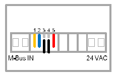
To configure the M-Bus Splitter, only the jumpers (short-circuit bridge) on the top edge of the M-Bus splitter.
Start up
- When the power supply is connected via either 24 VAC or M-Bus OUT2 power terminal, nothing happens. The diodes start flashing after about 1-3 minutes. It takes a while to load the circuits.
- After connecting all the buses both the input and the two outputs, it is necessary to scan the bus. You need to throw the yellow bridge and put it back. Then, you will wait about 10 minutes for an LED to flash on the M-Bus steadily. When scanning is connected, this LED will blink in 12 seconds. 1 blink means there is a meter on the bus, 2 means 2 counters, etc …
- Always leave the blue bridge at position 2 closed if the speed of the M-Bus is 2400 bd / s. (Usually it is)
- Black bridges 3 and 4 are always open. The M-Bus master will read the data from the counters on the M-Bus IN side every 1 minute.
- Always leave the red jumper in position 5 closed when the bus speed is on the M2 Bus OUT2 of 2400 bd / s (usually it is).
WARNING IN CASE OF PROBLEM !!!
- The cables must be connected correctly.
- The voltage to the M-Bus IN should be better than 23 V DC.
- The voltage to M-Bus OUT 2 should be better than 26 V DC.
- All bus-side meters connected to the M-Bus IN must have a single M-Bus primary address.
If problems persist, contact the Enectiva team.