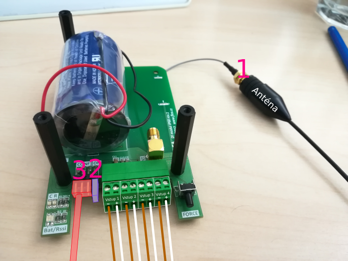
- Before starting, it is necessary to screw the antenna onto the connector on the module’s wire pin. Transmitting without an antenna could permanently damage the transmitter (1)
- Use the power jumper to connect the pins marked ON (2)
- Connect the USB cable supplied by the manufacturer to a free USB port on the computer and identify the marking of the corresponding COM port.
- Click on Start, type Device Manager in the Search Programs and Files field and open.
- Expand the Ports (COM and LPT) tab to find the assigned COM port number, e.g. COM7.
- Connect the other connector of the cable to the CONF pins. The 4 pins further away from the power jumper are used. (3)
Configuring the module using PUTTY
Configuration is done using any serial link communication program, we recommend the PUTTY program, which is freely downloadable on the Internet.
- Start PUTTY
- On the Session tab, set:
- Connection type to Serial
- Serial line to the name and number of our COM port (e.g. COM7) ** Speed to 115200
- On the Connection > Serial tab, set:
- Data bits to 8
- Stop bits to 1
- Parity to None
- Flow control to None
- Click Open button, a black terminal window will open. After pressing the enter key, DI4_@> is displayed, so the device is ready for communication.
List of commands to configure the module
This is a list of all possible commands. The individual commands are sent to the device by pressing the enter key.
helpdisplays all available commandsset t Xsets the transmission period to X minutes. For example,set t 15will set the transmission every 15 minutes.set c X Y Zsets the value of the IN X input (1-6), Y counter (1-2) to the Z value (0-4294967295). For example,set c 1 1 12345sets the first counter of the first input to the value 12345. This is described in more detail below.set ru GH EF CD ABsets the module ID in the radio network. Note that the individual pairs of digits are reversed. Thus, theset ru 45 23 01 00command sets the module ID to 12345. ID must be unique within the network (city, area)wrisaves the changes made to the module’s permanent memory. This must be done whenever the settings are changed!resetrestarts the device. This command can be executed, for example, if the module does not respond well to typed characters when it is first started (delay, skipping , or repeating characters).
Module settings
After installing the module in place, you need to configure the following:
show radio- displays the module ID. If this number is not unique in the site, it must be reconfigured using theset ru GH EF CD ABcommand. Note that each pair of digits is reversed. Thus, use theset ru 45 23 01 00command to set the module ID to 12345. Note down the ID, it is needed to activate reception from this module.- set the counter states according to the actual state of the meters
- Ex: the water meter has a state of 123,456 m3, 1 pulse = 1 l. It is connected to the first input. Set the counter with the command
set c 1 1 123456. - Example: the electricity meter has a state of 1234.5 kWh, 800 pulses = 1 kWh. It is connected to input 2. The counter is therefore set so that each pulse increases the value by 1. The state corresponds to 1234.5*800 pulses = 987600. Set the counter with the command
set c 2 1 987600. - The states and gear ratios should be recorded (or photographed) for later verification of the correct settings.
- Ex: the water meter has a state of 123,456 m3, 1 pulse = 1 l. It is connected to the first input. Set the counter with the command
show time- displays the transmission period. If a different period ofXminutes needs to be set, this is done using theset t Xcommand.- All settings must be written to the device’s permanent memory using the
wricommand.
Checking the settings
show di4displays the basic settings of the DI4 module - check the counter valuesshow radiowill show the broadcast settings - check that Channel 3, Data Rate 1 and correct ID are set