The converter is designed to galvanically separate the impulse outputs of the meter from the monitoring and control equipment. The device enables the separation of active consumption pulse, active supply pulse, reactive consumption pulse, reactive supply pulse and registration period pulse. The operation of each channel is monitored by coloured LEDs on both the input and output sides of the transmitter.
The wiring of the inputs is according to the following diagram, including the 230V power supply (terminals 1 and 2) and the connection of terminals 6 and 7.
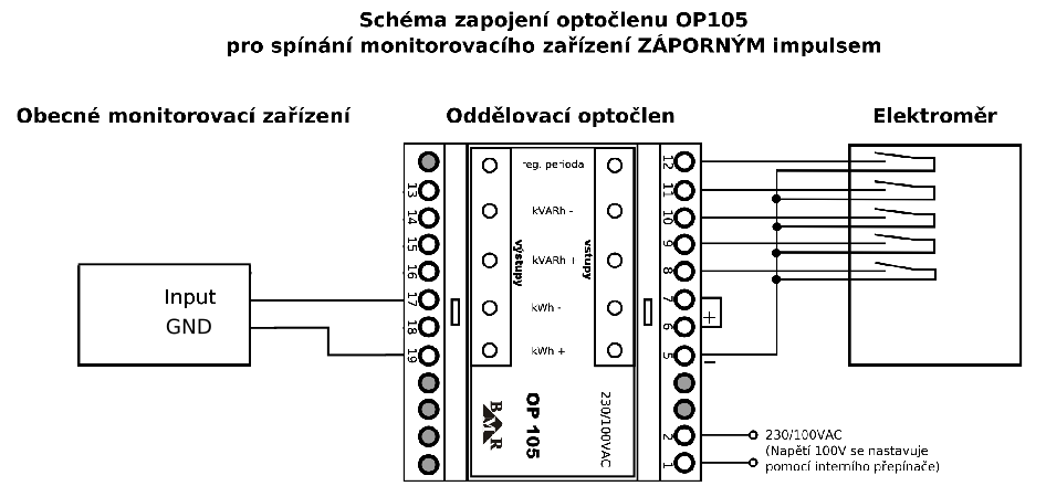
Most often, only the active consumption output is connected at terminals 17 and 19 without the 24V auxiliary supply.
Input terminal marking
- 1.2 230V AC power supply
- 5 - 24 V DC (internal power supply)
- 6 + 24 V DC (internal power supply)
- 7 + common plus
- 8 kWh+ active consumption
- 9 kWh- active supply or tariff
- 10 kVArh+ reactive consumption
- 11 kVArh- reactive supply
- 12 quarter-hour peak control period
Output terminal designations
- 19 COM Common pole
- 18 COMLED Output LED power supply
- 17 kWh+ active consumption
- 16 kWh- active supply or tariff
- 15 kVArh+ reactive consumption
- 14 kVArh- reactive supply
- 13 quarter-hour peak control period